This is the second part of an article series about integrating eval boards into a CI systems. In part 1 we took a look at why we would want to integrate eval boards into our CI system in the first place, and the physical environment our devices will have to live in.
In this part we will have a look at the local, computer-related support infrastructure of our eval boards.
Experiences
As with the experiences in part 1 of this series, following experiences are not all from a specific setup, but rather a collection of things encountered over the years.
Access to Your Devices
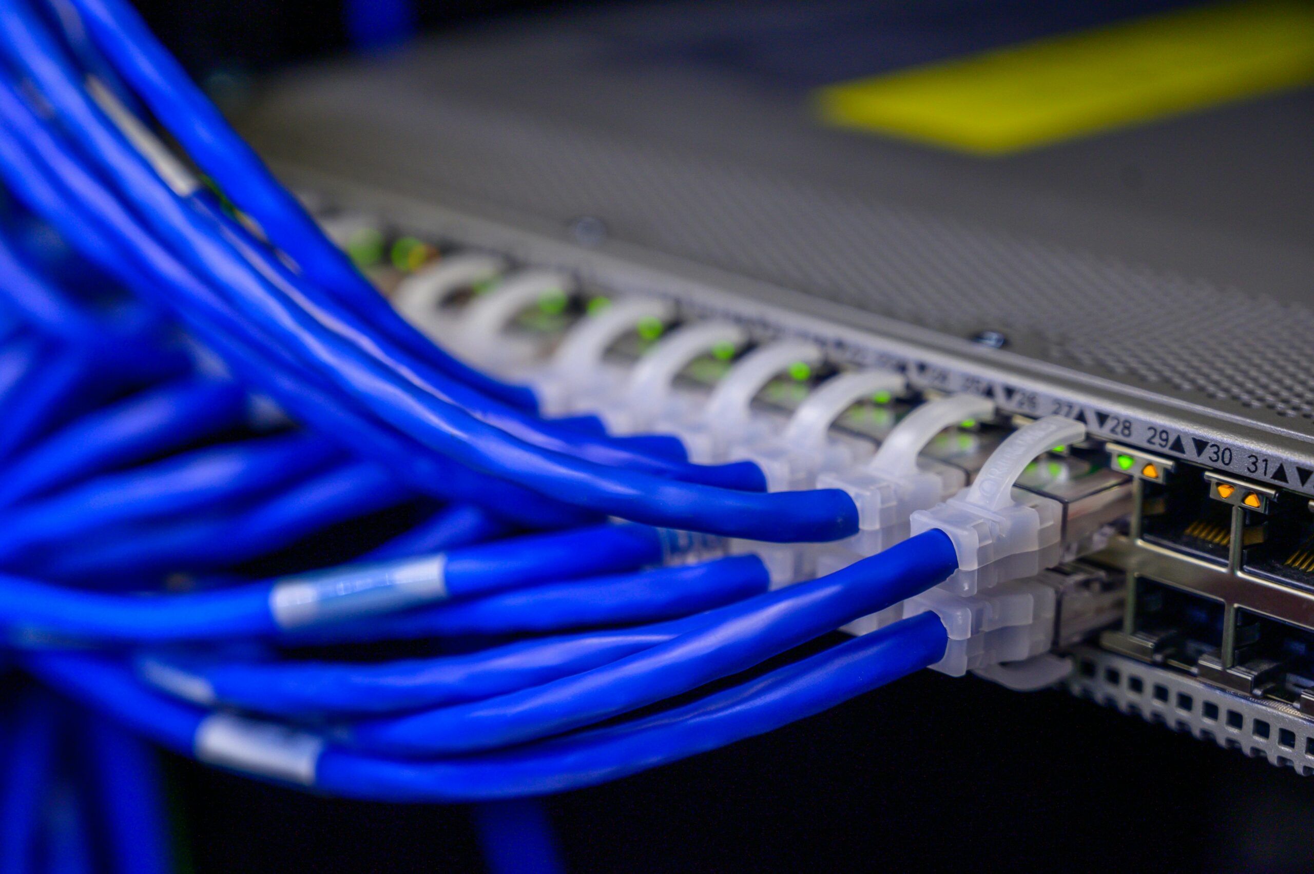
Eval hardware differs wildly in terms of connectors, but in my experience all devices need a USB connection, and only some need ethernet. Thus, you may need one or more PCs that your eval boards connect to. It’s mostly going to be USB ports that you need, and here mostly USB-A connectors, but of course that is slowly changing, so you might want to get some USB-A-to-C adapters, too (or a PC with additional USB-C ports).
If you have to create a private network (see part 1) this host (or hosts) will have to act as a “jump host” for connections to your eval boards. In this situation you will have to spec the host adequately, to allow it to hold test data for multiple users, and to be able to sustain the network throughput that may be needed.
Finally, while eval boards do come with the required USB cables most of the time, they do not always do so, so take that into account, too. As with ethernet cables, you don’t want to be blocked by a missing € 0.50 USB cable.
Controlling the Devices’ Power
You definitely want some easily remote controllable power outlets. Why? We need to be able to programmatically put our CI-integrated devices into a well-defined known-good state before each run. Most of the time that is going to be achieved via power-cycling the board. (“Have you tried turning it off and on again?”) Of course, eval boards can also simply hang. Maybe you poked a register you shouldn’t have poked, maybe your program entered an infinite loop, maybe a cosmic ray flipped a crucial bit in memory. But whatever the reason a quick power cycle almost always helps.
The majority of evaluation boards are hardwired to turn on as soon as they receive power. For our purposes this is a good thing1: If we can easily remote control a device’s power socket, we can control if and when the device is turned on or off. And “easy remote control” here means “easily done programmatically” via open APIs/protocols such as HTTP/Webhook or serial port/USB. If your CI logic is not implemented in a language that is supported by a provided API, then you should still be able to whip up a small shell script. Said shell script then fires off a quick HTTP call via cURL, or writes some bits to a serial port, et voilà!, your device is powered off or has been rebooted. (Of course the shell script dutifully reports the result of the requested actions via exit code. That is, after all, what they are there for.)
But what if your device receives power via USB? Well, if it has a dedicated USB power port and a separate USB port (or the like) over which communication is done this is easy. Just plug a USB power brick into a socket of your remotely controllable power outlet, and connect the device to that.
If both power and communication is done via the same USB port, things get a little more difficult, since you don’t have a remote-controlled power socket anymore. Enter uhubctl! Most modern computers can switch their USB ports on and off at will2. The intended purpose of this feature is to allow the OS to prevent a non-compliant device from drawing dangerous levels of power, but we can use that to control the device’s power and power-cycle it this way.
More complex devices can also be more complex to control, though. There is no general way that covers every device, so you will have to read the device’s documentation to come up with a way that suits it best3.
As a final hint: You may need to get replacement power cables and adapters, especially if your power outlets use C13 sockets4. You may even need y-cables or multiple-outlet power strips, as sometimes one device can come with multiple components, which then require multiple power sources and therefore multiple power sockets. In this case you still may want to use only one power socket on your remote controllable power outlet and split that socket into two (or more). If that is feasible, of course, and you don’t e.g. need to power one component of your device on before the rest.
Connection plan
You need to take care to have an up-to-date connection plan of which device connects where (power, USB, network, peripherals, etc.), because one day you might have to move to a different facility. And rebuilding everything might seem easy (and actually can be easy, depending on your device count), but what if it is not you doing the rebuilding? Or if you simply have too many devices to keep track of everything?
For this reason (and because it might not be you who has to recreate your setup) a detailed connection plan, possibly including photos, is always a good idea.
Shutdown and Startup
A well-documented shutdown and startup procedure is also a useful thing to have. Electrical safety certifications tend to pop up at the most inopportune times, but are required by law to take place regularly5. And scheduled power outages are a thing, too, as are unscheduled ones. This procedure should clearly state which devices need to be powered up and down in which order and how to do so: those remote controllable power outlets from before may require authentication and, at the same time, may not even have physical buttons to control each socket, is why.
And, again, it may not be you who powers everything up or down, but someone else.
Jumpers
Some devices may need to be controlled via jumpers, at least sometimes. E.g. they need to be set to one mode to flash, but another mode to execute the just-flashed code. For obvious reasons doing this manually is out of the question.
While the GPIO pins on a Raspberry Pi (or any other device) at first glance seem to be a solution, they really are not: They are meant for input and output (hence the name: general-purpose input/output), while jumpers just open or close a circuit. Thus, GPIOs behave fundamentally different: They might be floating, which may lead to undefined, possibly dangerous behaviour. Also, the voltage used for “closing” the circuit may be different than what is expected (think 3.3 vs 5 volt), which, again, may lead to undefined, possibly dangerous behaviour.
Thus, while Raspberry PI GPIO pins might work, they might also not. What will work are relays, so get some USB-controllable relays, some jumper cables, and tools like a wire cutter to set everything up. Using a relay, a circuit gets physically opened or closed, which is exactly what we want – unlike GPIOs as mentioned above. And if you select the relay board carefully you can program them in e.g. Python and thus the same applies as above for the power control: easy CI integration. Which, after all, is what we’re all about in this article.
Windows-only Devices
If at all possible steer clear of “Windows-only” devices, i.e. devices that require Windows to operate in any form or fashion. This might not be possible, but managing/running eval boards from a Linux host makes things much easier.
While you can easily just plug in any computer running Linux and access it via remote desktop (be it VNC or RDP) or SSH, the same cannot be said about Windows. Sure, Windows’ SSH capabilities have improved quite a lot over the recent years, and even allow concurrent multi-user logins. But chances are, that whatever tool you require will only work in a graphical session, even if that tool is text-only. And even if you think you’ll be fine with a graphical session there are added difficulties: Windows does not allow concurrent graphical multi-user logins6.
On top of that, your Windows installation might be set up to require a BitLocker disk-encryption PIN on bootup. You cannot easily change that to be able to input said PIN over a secure network connection, like you can on Linux7. And, of course, there is Windows’… “affinity” for rebooting after having an update applied.
So, faced with this exact scenario of having to use Windows for one of the devices we had to make available, we did the only thing we could:
- Enable graphical remote login via RDP. This can be done by adding users to the “Remote Desktop Users” group. We limited membership of this group to people who, for one reason or the other, absolutely needed to be able to log in.
- Make it clear to the users that they are supposed to log in, do their work, and log out again. On the other hand the users were also told that, if the login process would tell them that someone else is logged in, they should try to get hold of that someone and check with them if it is okay to log in (and thereby killing the existing login session) or not.
- Configure the PC to not require the BitLocker PIN when booting via the
Suspend-BitLockercmdlet. Not ideal, but we figured that the PC is in a locked, access-controlled room, so the security implications would be acceptable.
With regard to updates we couldn’t really do anything, but to accept the situation as-is and check if the device was available after each update.
Monitoring
Since a PR may be rejected based on the output of an eval board, you really want to make sure that this device is usable. For that you need to monitor it, and any monitoring is better than none. If you have no pre-existing monitoring system and are somewhat daunted by the task of setting one up, don’t be. Just use something like e.g. Uptime Kuma. If you have a monitoring solution, great!, use it for its intended purpose.
If the device in question has an operating system with a complete network stack, monitoring it is easy: just ping it, or check if SSH can be connected to. If that can’t be done try to ascertain if it is available in some other way. Maybe just see if it is present on the USB (e.g. via parsing lsusb output), or if it responds to a USB/serial connection. This is more involved, but certainly well worth the effort.
If the device is down, you might want to think about allowing PRs through, even if you cannot measure their performance. Otherwise, the whole development process might come to a standstill.
Ad-hoc access
Sometimes the best CI integration just won’t cut it. For those times you should keep a few devices available to your developers. Of course, not on their desks (at least not by default), but rather connected to a host reachable via the network with the device’s development environment set up and ready to use.
Be prepared, though, that this may require some fiddling with software. Since, as mentioned way at the beginning of this article, the software may be written with a single developer in mind, it may be difficult to make it “multi-user” aware. This may range from documentation giving you setup instructions that are wrong for our scenario, but easily fixable, to much more difficult problems, such as software trying to detect multiple instances of itself and refusing to run, even though the other instance belongs to a different user, or only picking up the first of multiple available devices8.
Also, you will have to instruct your developers on how to access this host, use the devices (possibly even having to go against the official documentation), and to coordinate so as to not step on each other’s toes.
Some tool chains I encountered used Docker to alleviate some of these problems, but the benefits and drawbacks of that are something to look at in a future article.
Summary
Integrating an eval board into the CI workflow is — relatively speaking — easy. The surrounding circumstances not so much. But while you may have a lot of things to keep in mind, it is all doable and manageable.
- One of the devices I encountered cost € 30,000 to € 50,000, yet the manufacturer chose a USB-to-serial chip with no integrated serial number, saving someting like € 0.50. Thus, when connecting more than one device whichever was connected first was
/dev/ttyUSB0, with later devices getting higher numbers. All fine and dandy until you had to reboot the host. Then it was anyone’s guess which device was which. Oh, and we had 11 of these things attached to this host. And since you couldn’t discern them via any unique, device-inherent property you also couldn’t write any udev rule to so. In the end we resorted to using the bus topology for the udev rules and stick-on labels on the USB hubs. ↩︎ - Things get a little more complicated, though, if you want or need to use USB hubs. Those mostly cannot be controlled via
uhubctl, with a select few exceptions. So, if at all possible, use internal USB ports or check the uhubctl list of compatible USB hubs. ↩︎ - One device I came across actually consisted of three interconnected devices: one low-spec control unit, and two high-spec “work horses”. The control unit could shut down the “work horses” independently either gracefully or forcibly. We used this capability, with a fall-back via the power plug. ↩︎
- In one case a very expensive device only came with C13-to-US-plug power cables. Easy enough to solve — if it hadn’t been for the fact that replacement cables were not available even with the IT on-site support. ↩︎
- The specific periods are device-class-dependent, but may be as often as once per quarter year. For office equipment, though, you should probably expect a certification every year, at least. ↩︎
- Not strictly true, but only Windows Server operating systems do. And those are expensive. Or you hack Windows with certain DLLs floating around the Internet, which opens you up to possible security issues, legal issues and the OS trying to fight you for your own sake, because its files were altered. Not fun. ↩︎
- Of course, Windows can be configured to not require any BitLocker password if it is booted inside the correct network (via “Network Unlock”). But that requires, both, the correct setup on the client and on the servers. If that’s neither already in place, nor in the cards, then there is no alternative, but to enter the PIN manually on bootup. ↩︎
- One of the devices I encountered cost € 30,000 to € 50,000, yet the manufacturer chose a USB-to-serial chip with no integrated serial number, saving something like € 0.50. Thus, when connecting more than one device whichever was connected first was
/dev/ttyUSB0, with later devices getting higher numbers. All fine and dandy until you had to reboot the host. Then it was anyone’s guess which device was which. Oh, and we had 11 of these things attached to this host. And since you couldn’t discern them via any unique, device-inherent property you also couldn’t write any udev rule to so. In the end we resorted to using the bus topology for the udev rules and stick-on labels on the USB hubs. ↩︎


One thought on “Integrating Development Hardware into a CI Workflow – Part 2”
Comments are closed.